mail_outline sales@mediastorehouse.com
1,906 Items
Untitled mechanism, front and side elevations Date: 1853
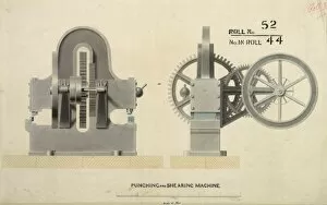
Punching and shearing machine, front and side elevations Date: 1853
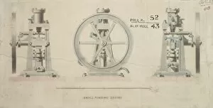
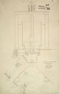
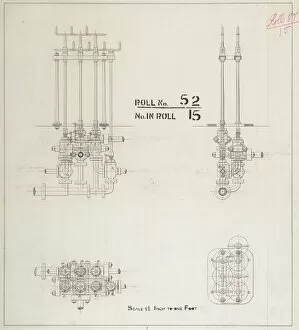
Small pumping engine, front and side elevations
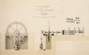
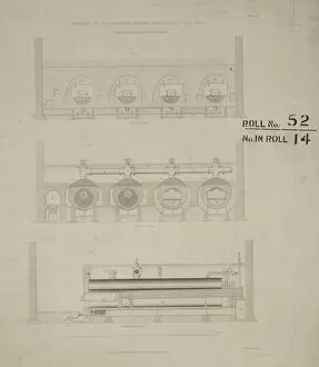
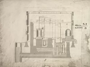
30 hp high pressure engine directly applied to rolls, front and side elevations Date: 1851
Automatic speed regulator
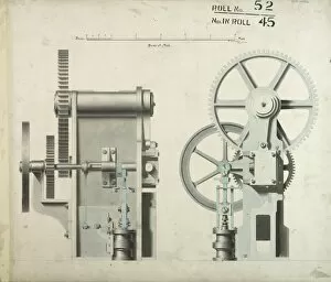
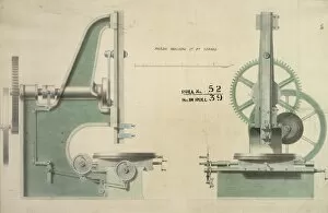
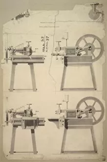
Paring machine, 1ft 4 in stroke, front and side elevations
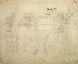
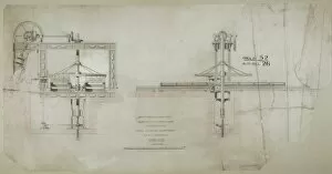
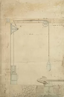
Boring mill as adapted for a corner of a shop, plan, side elevation and detail Date: 1848
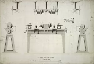
Patent double lathe 5 inch centres, front and side elevations and details Date: 1857
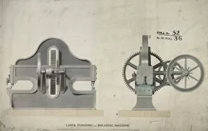
Large punching and shearing machine, front and side elevations Date: 1853
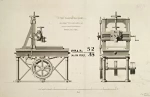
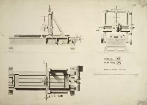
3 feet planing machine, front and side elevations Date: 1849
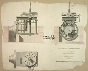
Patent portable key grooving machine, plan, front and side elevation Date: 1849
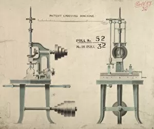
Patent grooving machine, front and side elevations Date: 1854
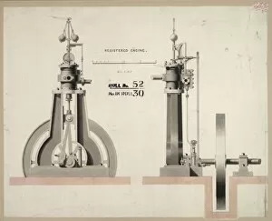
Registered engine, front and side elevations
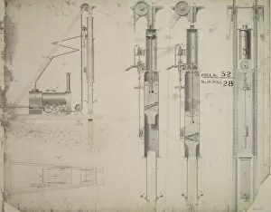
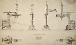
Untitled, steam pile driving machinery, plan, elevation and sections
Small lever planing machine, front, back and side elevations Date: 1841
Improved fly-planing machine as employed at the Royal Carriage Department, front and side elevations
6 feet planing machine, plan, front and side elevations Date: 1858
Punching and shearing machine, front and side elevation with detail
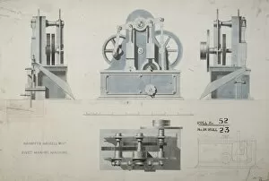
Rivet making machine, plan, front and side elevations and section Date: 1848
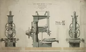
Improved radial drilling machine, plans, front, back and side elevations Date: 1848
Small lever planing machine, front and side elevations Date: 1841
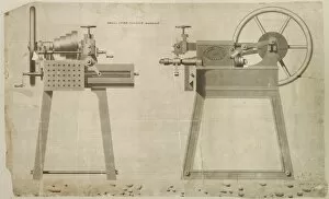
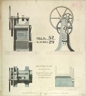
Bar cutting machine, plan, front and side elevations and detail Date: 1848
Large paring machine 2ft 6 in stroke, front, back and side elevations Date: 1849
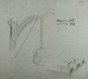
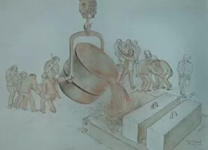
Safety ladle showing crane mounting
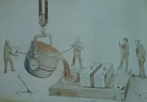
James Nasmyths safety ladle invented February 1835 Date: 1862
Old style ladle for pouring molten metal Date: 1862
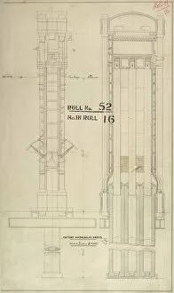
Untitled, hydraulic press, details
Patent hydraulic press, vertical sections Date: 1862
Untitled, patent hydraulic press
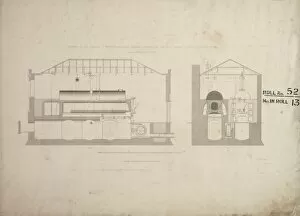
Boilers of the Cornish engine erected at Old Ford Date: 1842
Boulton and Watt waggon-head boilersSections of the Boulton and Watt waggon-head boilers erected at the East London Water Works Date: 1842
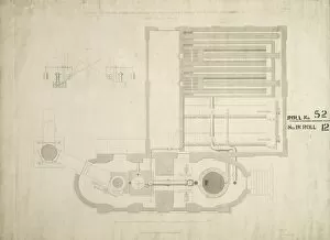
Cornish engine and boilers - East London Water Works
Cornish engine and boilers - East London Water WorksPlan of the Cornish engine and boilers erected at the East London Water Works, Old Ford Date: 1842
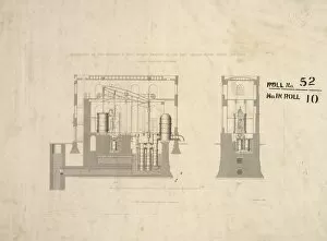
Boulton and Watt engine - East London Water WorksElevation of the Boulton and Watt engine, erected at the East London Water Works, Old Ford Date: 1842
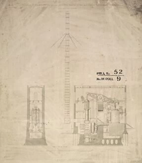
Cornish engine and stand pipe - East London Water WorksElevation of the Cornish engine and stand pipe erected at the East London Water Works, Old Ford Date: 1842
Boulton and Watt engine - East London Water WorksLongitudinal section of the Boulton and Watt engine erected at the East London Water Works, Old Ford Date: 1842
Steam hercules, plan and side elevation Date: 1846
Steam hercules, rough pencil sketch Date: 1846
Steam hercules, side elevation Date: 1846
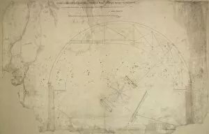
Mounting the proposed 4 feet apeture reflecting telescopeDesign for equatorially mounting the proposed 4 feet apeture reflecting telescope, side elevation Date: 1853
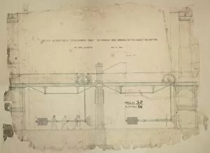
Design for a steam hammer forge for wrought iron ordnance of the largest description, side elevation
Machine for cutting the key grooves on railway axles, front and side elevations
Wilsons steam engine, mechanical details, sheet 2
Wilsons steam engine, side elevation and details
Stamp hammer for Mr Walton, front and side elevations and details
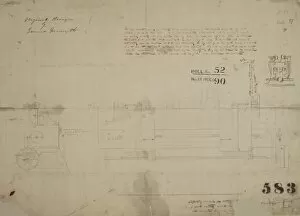
J Nasmyths patent steam hammer, front elevation and details
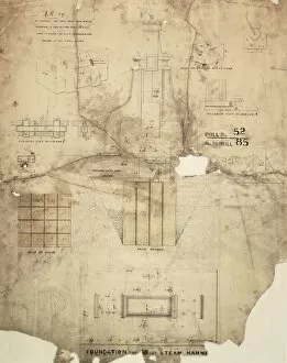
Foundation for a 30 cwt steam hammer, plan, front elevation and details
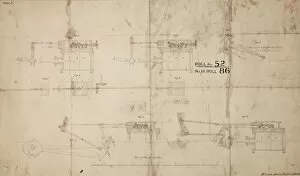
Foundation for 30 cwt steam hammer, plan, front elevation and details Date: 1856