mail_outline sales@mediastorehouse.com
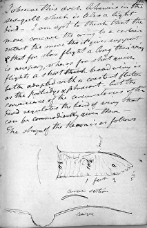
Royston crow cross-section - 1808sRoyston crow cross-section. 1808. From Cayleys original notebook
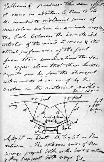
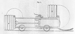
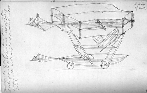
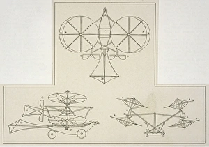
First compound aeroplane design, with flappers mounted on struts rising from fixed wings set dihedrally on a wheeled car. 1805. From Cayleys original notebook
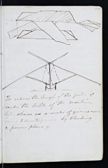
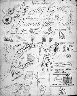
Page from the original notebook of George Cayley (1773-1857) - prolific English engineer and one of the most important people in the history of aeronautics. Date: 1808
Cayley exercise book inside back coverCayley exercise book, inside back cover
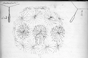
Sketch of Garnerins parachute (left)Left: Sketch of Garnerins parachute. Right: Sketch of a bladed parachute suggested by the Goatsbeard fruit. Design Illustration from Cayleys original notebook
A sketch of Goatsbeard and two diagrams of fruit parachuting. Design Illustration from Cayleys original notebook
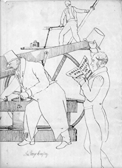
Cayleys Air Engine put up in the Brew House at Brompton, showing Wadeson and Vick, his mechanics, Sir Goldsworthy Gurney, Sir George Cayley and Edward Cayley, MP
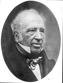
Sir George Cayley (1773-1857)Sir George Cayley, 1773-1857
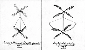
George Cayleys 1796 helicopter modelRight: George Cayleys 1796 helicopter model: the contra-rotating rotors are feathers stuck in corks, operated by a bow-string
Page of letter from Robert B Taylor to Sir George CayleyPage of letter from Robert B. Taylor to Sir George Cayley, 25 July 1842
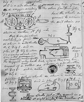
George Cayleys designs for a universal railway. 1825
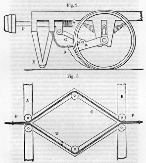
George Cayleys design for a train brake system. 1841
George Cayleys design for a train buffer. 1841
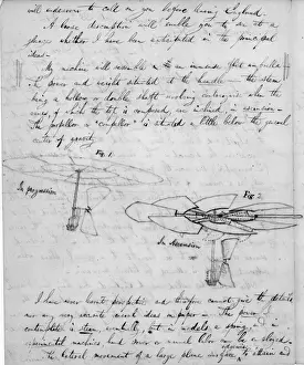
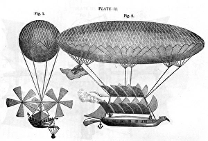
George Cayleys third design for an airship, showing, left, head-on view with airscrew propulsion and, right, side view with flapper propulsion. 1817. Shown here as re-engraved on 4 March 1837
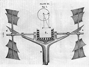
George Cayleys design (side elevation) for contra-rotating tandem airscrews for airship propulsion; the airscrews have curved blades mounted on rods radiating from the hubs; the whole mounting can be
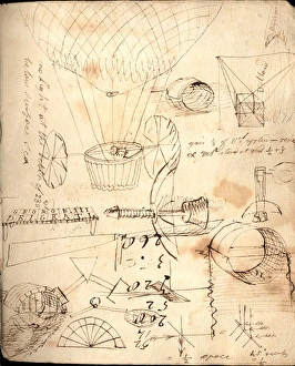
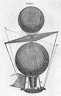
George Cayleys design for a double balloon to be propelled by inclining a plane between the two envelopes. 4 March 1837
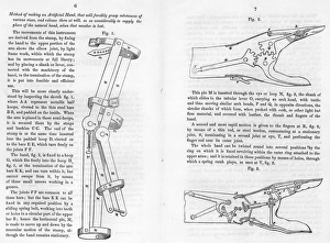
George Cayleys design for an artificial hand. March 1845
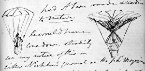
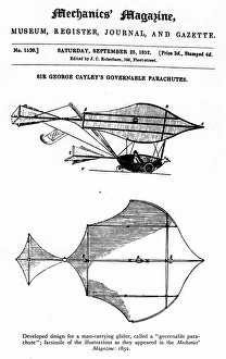
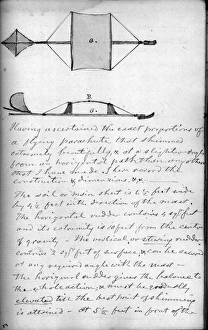
George Cayleys governable parachute. Developed from a design for a man-carrying glider, called a governable parachute. Facsimile of the illustrations as they appeared in Mechanics magazine
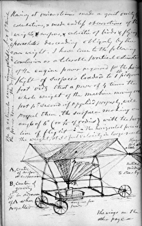
George Cayleys design for a convertiplane Front elevationGeorge Cayleys design for a convertiplane. Front elevation (without airscrews) and plan. 8 April 1843
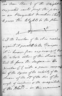
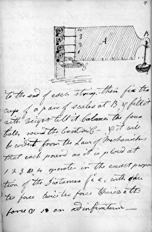
The forces of flight 1795 From Cayleys original notebookThe forces of flight. 1795. From Cayleys original notebook
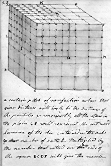
Cube 1795 From Cayleys original notebookCube. 1795. From Cayleys original notebook
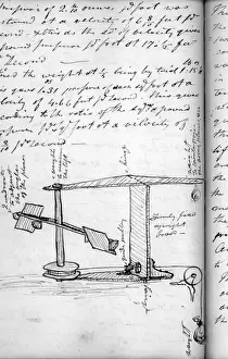
Testing the strength of a wooden plane 1795Testing the strength of a wooden plane. 1795. From Cayleys original notebook
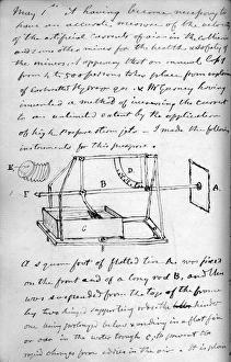
Sketch of the third whirling arm 1818Sketch of the third whirling arm. 1818. From Cayleys original notebook
Design for a compound tandem machine with flappers mountedDesign for a compound tandem machine, with flappers mounted outboard of the fixed wings: flappers a move up, as BB move down. 1815. From Cayleys original notebook
Ropemaker 1812 From Cayleys original notebookRopemaker. 1812. From Cayleys original notebook
Plan and side views of the improved riding rudder glider model. 1853. From Cayleys original notebook
Glider flights 1853 From Cayleys original notebookGlider flights. 1853. From Cayleys original notebook
Sketch of the 1849 boy-carrying machine showing the triplane wing structure, tail-unit, and wheeled car with pilot-operated elevator-cum-rudder, and propulsive flappers. 1853
1849 boy-carrier showing the dihedral(a) Rear view of the 1849 boy-carrier, showing the dihedral angle of the triplane wings, and imaginary flappers of bird-wing form; (b) the favoured form of propulsive flappers in 1853
Large whirling arm used for testing aerofoilssLarge whirling arm used for testing aerofoils of 10sqft area. 1850. From Cayleys original notebook
Gunpowder engine model 1850sGunpowder engine model. 1850. From Cayleys original notebook
Sketch of a swinging plate anemometer 1849sSketch of a swinging plate anemometer. 1849. From Cayleys original notebook
Frontispiece to Motive Power 1793sFrontispiece to Motive Power. 1793. From Cayleys original notebook
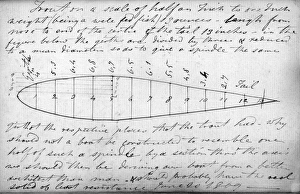
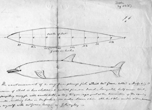
Design for a solid of least resistancesDesign for a solid of least resistance, based on the form of a trout. 1809. From Cayleys original notebook
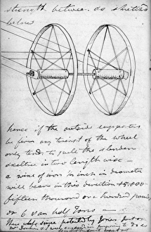
Two tension wheels shown in perspectivesTwo tension wheels shown in perspective. 1808. From Cayleys original notebook
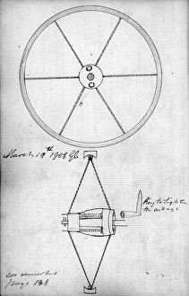
First design for the tension (or suspension) wheelsFirst design for the tension (or suspension) wheel for aircraft undercarriages: (a) side elevation; (b) cross-section, with section of the key for tightening the cordage. 1808
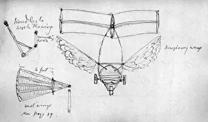
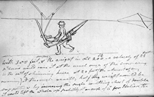
Sketch of the car for an ornithopter showing the flappersSketch of the car for an ornithopter, showing the flapper transmission and the seat and foot-rest for the pilot. 1808. From Cayleys original notebook
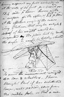
First design for an ornithopter showing the flappersFirst design for an ornithopter, showing the flappers in the down-position and the counterpoises (above) in the up-position. 1808. From Cayleys original notebook
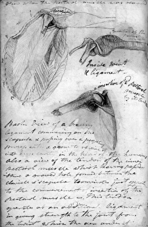
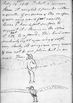
Diagrams of a herons wing: (a) plan view; (b) wing section; (c) rear view, to show lateral curvature. 1808. From Cayleys original notebook
Sketches of a heron (rear view) with wings extended. 1808. From Cayleys original notebook
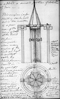
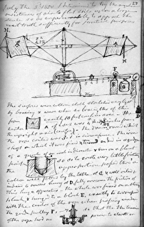
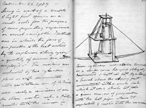
Small experimental gunpowder engine, showing the bow string mechanism to effect the return stroke of the piston. 1807. From Cayleys original notebook
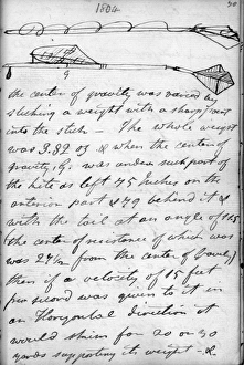
Model glider; a kite mounted on a pole (with a weight beneath), and a cruciform tail unit attached by a universal joint. 1804. From Cayleys original notebook
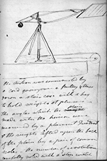
Whirling arm for testing aerofoils, rotated by a weight and cord over a pulley. 1804. From Cayleys original notebook
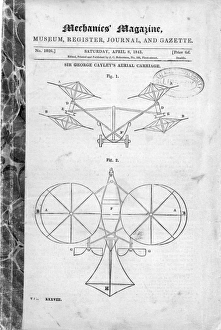
Sir George Cayleys drawingsSir George Cayley manuscript illustration. From: C.H. Gibbs-Smith Sir George Cayleys Aeronautics 1796-1855 (London: HMSO/Science Museum)
Cayley exercise book inside front coverCayley exercise book, inside front cover
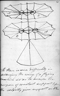
Cayleys HelicopterCAYLEYs HELICOPTER-AEROPLANE With two lateral helicopter rotors to provide lift, and two propellers for propulsion, this is an astonishingly far- sighted proposal