mail_outline sales@mediastorehouse.com
1,906 Items
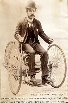
Edward Butler steering his petrol Tri-car at Erith 1889 Date: 1889
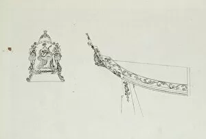
Steam yacht Caledonias stern decorationSketch of the steam yacht Caledonias stern decoration Date: 1815
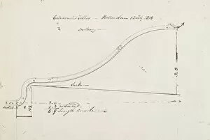
Tiller of the steam yacht Caledonia, Rotterdam Date: 1818
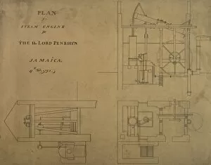
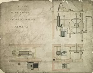
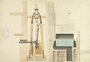
Steam engine for the Hon Lord Penrhyn, Jamaica
Steam engine for the Hon Lord Penrhyn, JamaicaPlan of a steam engine for the Hon Lord Penrhyn, Jamaica Date: 1796
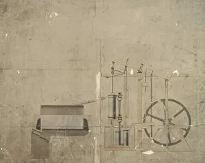
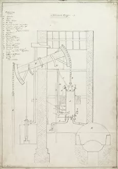
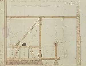
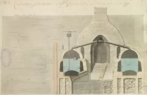
General section of Mr Illingworths engine no 2 Date: 1792
General section of Mr Illingworths engine no 2
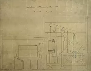
General view of engine and cross section, unidentified
Engine and cross-sections of the boilers, Regulator Mill CoGeneral view of engine and cross sections of the boilers, Regulator Mill Company
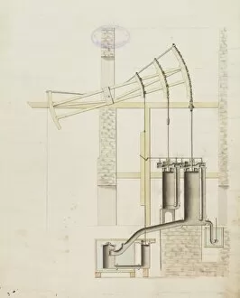
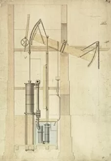
Engine and section of the boilers, Borough Water WorksFront view of the engine and section of the boilers, Borough Water Works Date: 1796
General view of the engine, Borough Water Works Date: 1796
Plan of the engine and boiler, Borough Water Works Date: 1796
Engine for Messrs Peels, Ainsworth and CoPlan of an engine for Messrs Peels, Ainsworth and Company, 5 April 1787 Date: 1826
Newcomens engine, unidentified drawing Date: 1826
Newcomens engine, drawing no 4 Date: 1826
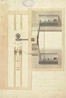
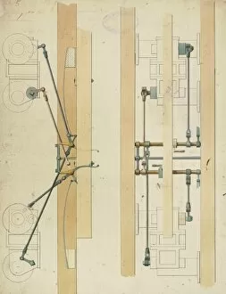
Plan of the engine taken above the working beam Date: 1795
Ground plan of the engine, boilers Date: 1795
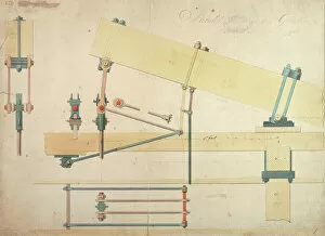
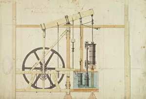
Boulton and Watt steam engine with planetary gear, 1795 Date: 1795
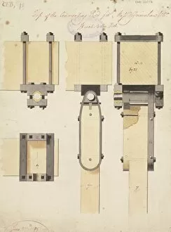
Top of the connecting rod Date: 1795
Gear, front and side view
Longitudinal section of the boiler houses and chimneys Date: 1795
Cross section of engines and boiler houses Date: 1795
Side view of the engine framing Date: 1795
Cross section of the boilers Date: 1795
Front view of the engine Date: 1795
Edge view of the rotative motion Date: 1795
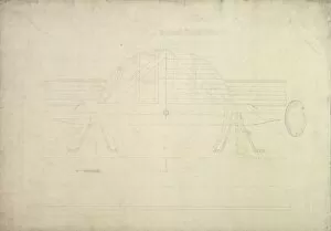
General view of the engine Date: 1795
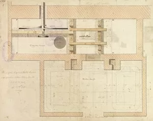
Plan of the engine and boiler houses Date: 1795
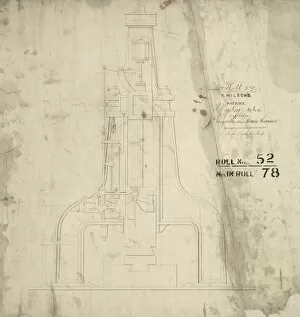
R Wilsons patent self acting motion as applied to J Nasmyths 30 cwt steam hammer, front elevation
10 cwt steam hammer, front elevation Date: 1845
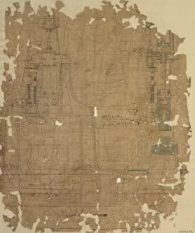
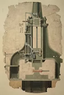
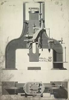
J Nasmyths patent steam hammer, plan, front and side elevations
J Nasmyths patent steam hammer, front and side elevations Date: 1852
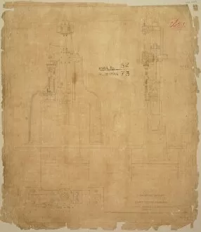
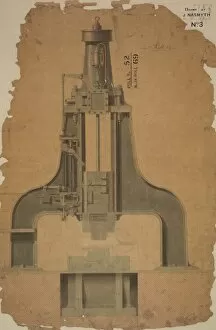
J Nasmyths patent 1 cwt steam hammer
J Nasmyths patent steam hammer, front and side elevations
Nasmyth steam hammer, c1847 Date: 1847
Anvil and base plate for a 25 cwt steam hammer, plan, front elevation and details
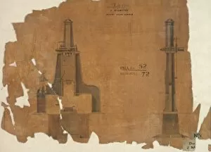
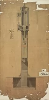
J Nasmyths patent steam hammer, side elevation and part section
J Nasmyths patent steam hammer, front elevation
2 ton steam hammerFoundation, base-plate, anvil for a 2 ton steam hammer, plan elevation and details Date: 1847
5 cwt steam hammer, J Nasmyths patent, front elevation and detail
Anvil and base plate for 80 cwt steam hammer, plan, elevation and details Date: 1850
Steam hercules with Wilsons patent valve, side elevation Date: 1851
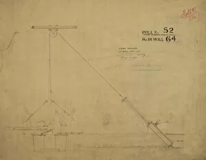
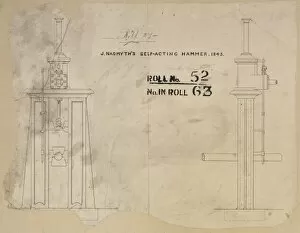
J Nasmyths self-acting hammer Date: 1843
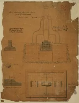
Wilsons patent no 11, 767 steam hammerWilsons patent (no 11, 767 steam hammer improvements) plan and elevation Date: 1847
Wilsons patent no 11, 767 steam hammerWilsons patent (no 11, 767 steam hammer improvements) front and side elevations Date: 1847
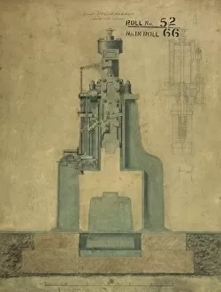
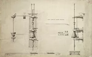
Great vertical boring machine, front and side elevations Date: 1849
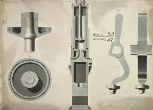
Wilsons patent no 11, 767 steam hammerWilsons patent (no 11, 767 steam hammer improvements) details Date: 1847