mail_outline sales@mediastorehouse.com
1,906 Items
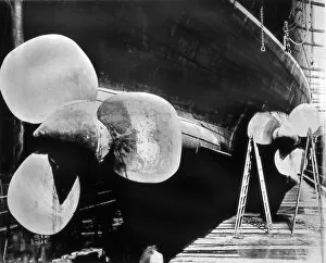
Propeller from the Lusitania steamship
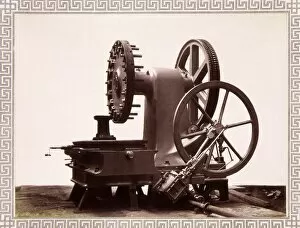
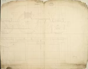
Armour plate milling machine, 1870s Date: 1870
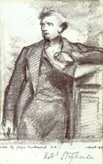
Robert Stephenson (1803-1859) sketch
Steam turbine blades - Sir Charles ParsonsSteam turbine blades from an early sketch by Sir Charles Parsons, 1897 Date: 1897
IMechE Storeys Gate building HQ, 1910IMechE Storeys Gate (address later Birdcage Walk) building HQ, 1910 Date: 1910
IMechE Birdcage Walk HQ building entrance, 2007 Date: 2007
IMechE Birdcage Walk HQ building 2007 Date: 2007
IMechE Birdcage Walk HQ building 2009 Date: 2009
Institution of Mechanical Engineers, Birdcage Walk, Spring 2009 Date: 2009
Bleriot monoplane in flight c1909 Date: 1909
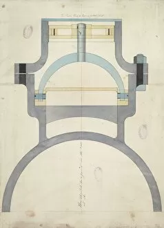
Steam cylinder and piston section
Steam cylinder sections
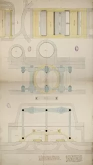
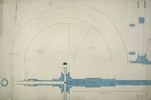
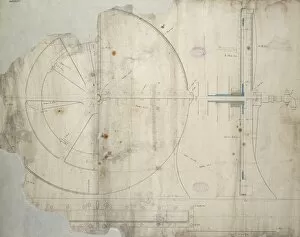
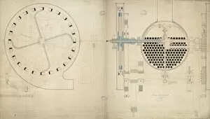
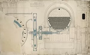
Centrifugal engine, Drawing no 3Centrifugal engine, drwaing no 3, wheel elevation and sections 5 November 1849 Date: 1849
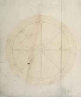
Centrifugal engine, wheel elevation
Centrifugal engine
Andrews engine, with wheel section
Andrews engine, general arrangement
Steam turbine locomotive engine, wheel section
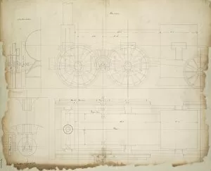
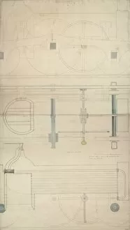
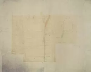
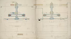
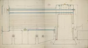
Steam turbine locomotive engine, plan, side elevation, half cross section and detail
Steam turbine locomotive engine, plan, side elevation, cross section and detail of roller Date: 1849
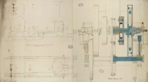
Steam turbine locomotive engine, plan, side elevation and cross section 18 March 1849 Date: 1849
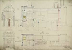
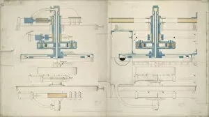
Detail of a steam turbine locomotive, with side elevation and vertical and longitudinal sections Date: 1848
Detail of a steam turbine locomotive, turbine arrangement section and locomotive cross section Date: 1848
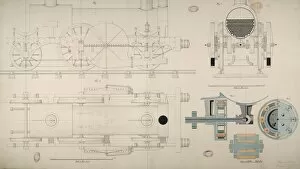
Locomotive engine, longitudinal, horizontal and cross sections Date: 1859
Locomotive engine, longitudinal section Date: 1850
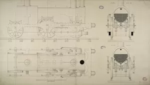
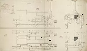
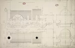
Locomotive engine, 6 foot 6 inch driving wheel, plan, side elevation and cross sections 15 May 1849 Date: 1849
Locomotive engine, 6 foot 6 inch driving wheels, cross sections 3 April 1849 Date: 1849
Locomotive engine, section
Locomotive engine, plan and side elevation
Locomotive engine, 9 foot driving wheel, horizontal and cross sections 1 June 1849 Date: 1849
Locomotive engine, 6 foot 9 inch driving wheel, cross section
Locomotive engine, 5 foot 9 inch driving wheel, plan, side elevation, half elevations and sections
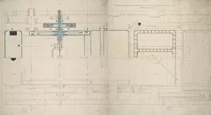
Locomotive tank engine, 4 foot 9 inch driving wheel, longitudinal section 4 May 1849 Date: 1849
Locomotive tank engine, 4 foot 9 inch driving wheel
Locomotive tank engine, 4 foot 9 inch driving wheel, plan and section 4 May 1849 Date: 1849
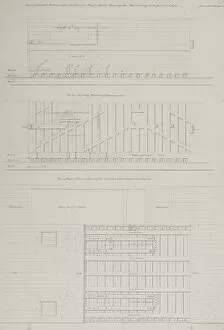
Centrifugal marine engine and boilers, 500hp, side elevations and sections 5 January 1849 Date: 1849
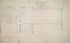
Boiler, 500hp boiler, side and front elevations with sections, 4 December 1848 Date: 1848
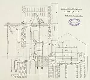
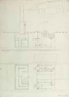
Working gear for the Warwick and Birmingham canal
Engine, Warwick and Birmingham Canal
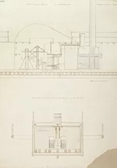
Caledonia steam boat, side view of an engine, cross section with front view of the boilers Date: 1817
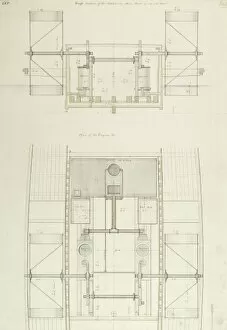
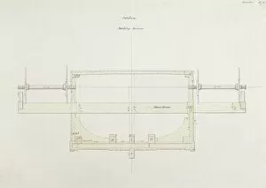
Cross section of the Caledonia steam engines and plan of the engines Date: 1817
Caledonia steam yacht sketch, a scheme for two 14 horse engines working at right angles Date: 1817
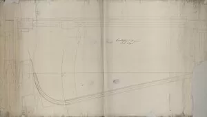
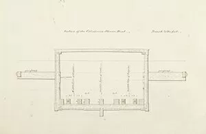
Section of the steam yacht Caledonia Date: 1817
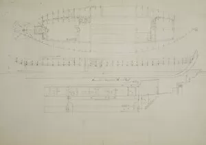
Steam yacht CaledoniaLongitudinal section, section and plan of the steam yacht Caledonia Date: 1817
Steam yacht Caledonias midship section, London Date: 1817
Dimensions of the steam yacht Caledonia Date: 1817
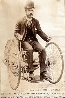
Edward Butler steering his petrol Tri-car at Erith 1889 Date: 1889